Description
BNC CONNECTORS
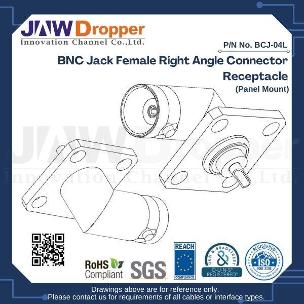
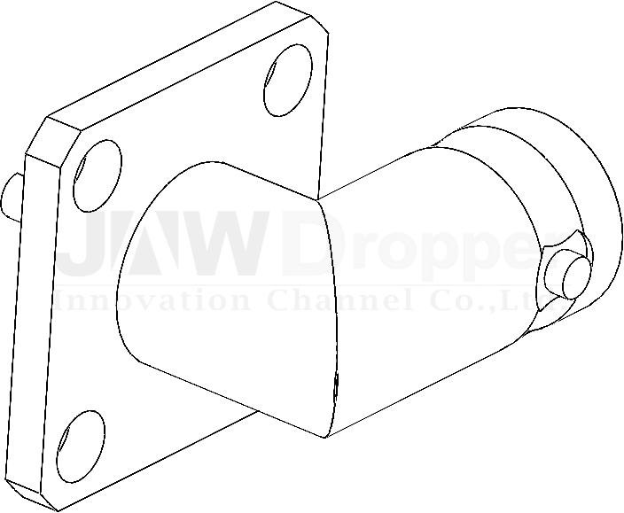
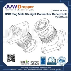
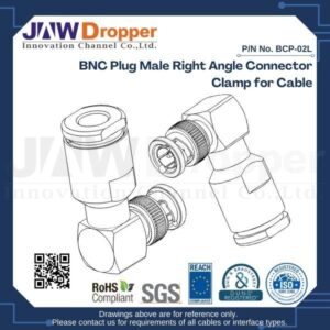
The BNC RF connector series features a bayonet-style coupling mechanism that enables effective connection/disconnection with proper locking. Mating is fully achieved with a quarter-turn of the coupling nut. With a classic, dependable design, BNC RF connectors are used with miniature-to-subminiature coaxial cable in radio, television, and other radio-frequency electronic equipment, test instruments, and video signals. BNC connectors are most commonly made to match the characteristic impedance of cable at 50 ohms or 75 ohms. With a standard and trustworthy design, RF BNC connectors are capable of accommodating a large variety of RG and industry-level coaxial cables in diversified termination styles.
FEATURES AND BENEFITS
- Bayonet coupling mechanism provides proper and effcictive mating and un-mating
- 50 and 75 ohm impedance designs allow customers to match impedance to system requirements
- Connectors are available for military, industrial, and commercial applications
- Designs available for a variety of common BNC coaxial cable types
- BNC jack female and plug male configurations
APPLICATIONS
- Antennas
- Broadcast (50 / 75 Ω)
- Telecommunications
- Automotive
- Computers/LANs
- Medical Equipment
- Satcom
- Base Stations
- Cable Modems
- Instrumentation
- Military/Aerospace
BNC CONNECTOR SPECIFICATIONS
| BNC Connectors Specifications – 50Ohm | |
| Impedance | 50 Ohm |
| Frequency Range | DC – 4 GHz (DC -12 GHz on Extended Range Designs) |
| Voltage Rating | 500 Volts RMS Max Continuous |
| Dielectric Withstanding Voltage | 1500 VRMS Max |
| VSWR (Return Loss) | |
| DC – 4 GHz | 1.3 (-18 dB) Max |
| Insulation Resistance | 5000 MΩ Min |
| Center Contact Resistance | 1.5 mΩ Min |
| Outer Contact Resistance | 0.2 mΩ Min |
| RF Leakage | 55 dB Max @ 3 GHz |
| Insertion Loss | 0.2 dB Max @ 3 GHz |
| Power Handling | 316 W Max @ 1 GHz @ 25 ºC |
| BNC Connectors Specifications – 75Ohm | |
| Impedance | 75 Ohm |
| Frequency Range | DC- 4 GHz (DC – 12 GHz on Extended Range Designs) |
| Voltage Rating | 500 Volts RMS Max Continuous |
| Dielectric Withstanding Voltage | 1500 VRMS Max |
| VSWR (Return Loss) | |
| DC – 4 GHz | 1.5 (-14 dB) Max |
| 12G Products: DC – 6 GHz | 1.22 (-20 dB) Max |
| 12G Products: 6 – 12 GHz | 1.43 (-15 dB) Max |
| Insulation Resistance | 5000 MΩ Min |
| Center Contact Resistance | 1.5 mΩ Min |
| Outer Contact Resistance | 0.2 mΩ Min |
| RF Leakage | 55 dB Max @ 3 GHz |
| Insertion Loss | 0.2 dB Max @ 3 GHz |
| Power Handling | 316 W Max @ 1 GHz @ 25ºC |
Note: These characteristics are typical and may not apply to all connectors.