


Descripción
PRODUCT OVERVIEW
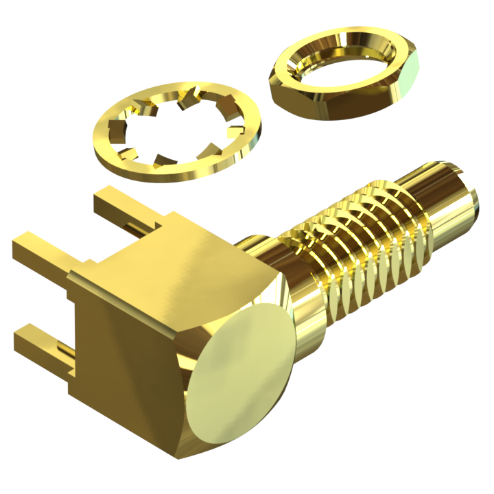
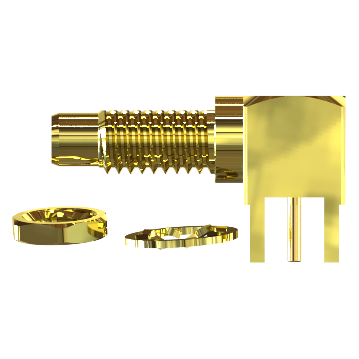
The SMCJ-06AL-BT-01-Au is a 50 Ω SMC Jack (Male Pin) receptacle for RF connections from DC to 4 GHz. It combines a subminiature threaded mating interface with a right-angle PCB connection and bulkhead rear mounting, providing a compact way to connect a circuit board to an RF port at an equipment panel.
The right-angle geometry routes the mating connection perpendicular to the PCB contact pin. This arrangement is useful when the circuit board sits behind a front or rear panel and the RF connection must be accessible from outside the enclosure. A 7.00 mm square body, 20.15 mm overall length and 11.45 mm overall height provide defined dimensions for board and enclosure planning.
The threaded SMC interface uses screw-on mating engagement. The assembly includes a nut and teeth washer for the panel mounting arrangement, with a maximum panel thickness of 2.80 mm. The drawing provides both the PCB hole pattern and the D-shaped panel opening so that the electrical connection and mechanical mounting can be designed together.
Gold-finished brass bodies and a gold-finished brass contact pin are combined with PTFE insulators. The specified temperature range is −65 °C to +165 °C, and the assembly weighs 4.28 g. These details support component selection for compact RF instruments, communication equipment and board-mounted RF modules. Use the 2D drawing and Data Sheet to review the mating interface, installation dimensions and electrical ratings for your design.
Features
- 50 Ω RF connectivity from DC to 4 GHz: Provides a defined impedance and operating frequency range for RF signal connections between a PCB assembly and mating equipment.
- Threaded SMC engagement: The screw-on interface provides positive mechanical retention when mated. This is useful where the design calls for a threaded connection that is deliberately coupled and uncoupled.
- Compact installation envelope: The 7.00 mm square body helps accommodate an RF port in equipment with limited board or panel space. The drawing includes overall dimensions for checking adjacent components and enclosure clearance.
- Right-angle board connection: Changes the connection direction between the mating interface and PCB contact pin, supporting layouts where the RF port faces an enclosure panel.
- Bulkhead rear mounting: Combines PCB termination with a panel mounting arrangement for panels up to 2.80 mm thick. The included nut and teeth washer are identified in the complete drawing BOM.
- Gold-finished brass construction: The brass contact pin and body components have a gold finish. PTFE insulators separate the signal contact from the surrounding connector body.
- Detailed installation documentation: PCB hole locations, contact pin diameter, panel cutout dimensions and general drawing tolerances are available for mechanical and PCB layout review.
Key Technical
- Series and interface: SMC Jack (Male Pin), with a threaded mating connection.
- Impedance: 50 Ω; select the mating connector and RF transmission path for the intended system impedance.
- Frequency range: DC to 4 GHz. The complete RF path also depends on the mating connector and PCB transition design.
- Thread designation: #10-32 UNF-2A as shown on the product drawing.
- Connector configuration: Right-angle PCB receptacle with bulkhead rear mounting.
- Electrical ratings: Working voltage 335 Vrms; dielectric withstanding voltage 1,000 Vrms; insulation resistance 1,000 MΩ.
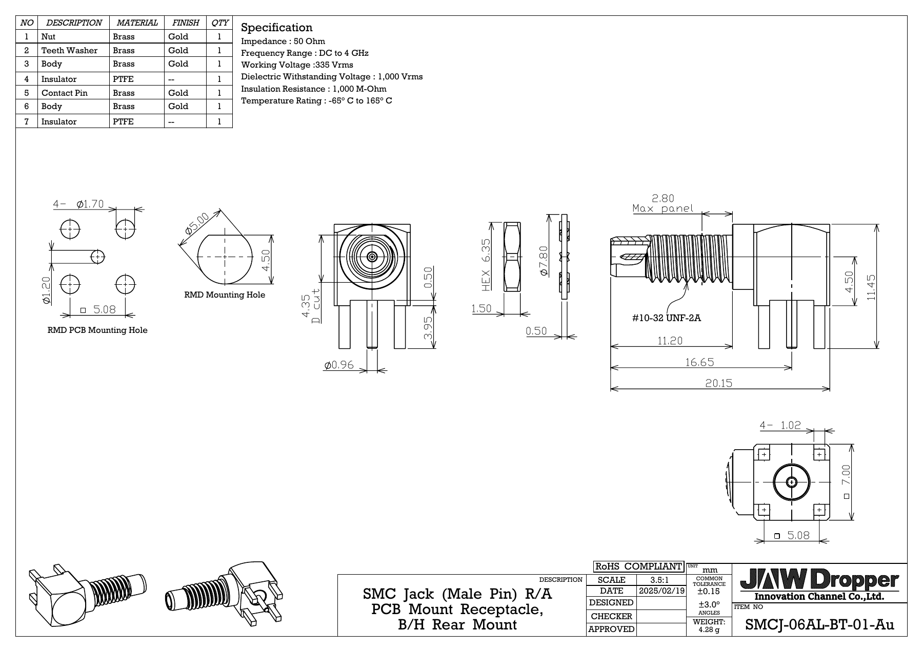
- Body and overall dimensions: 7.00 mm square body; 20.15 mm overall length; 11.45 mm overall height.
- PCB mounting pattern: 5.08 mm square pattern with four Ø1.70 mm holes. The PCB center hole is Ø1.20 mm and the contact pin diameter is Ø0.96 mm.
- Panel mounting: Maximum panel thickness 2.80 mm; panel opening Ø5.00 mm with a 4.50 mm flat. Check the drawing for the cutout profile and mounting arrangement.
- Materials and finishes: Gold-finished brass bodies, contact pin, nut and teeth washer; PTFE insulators. Individual components are listed in the BOM below.
- Temperature and weight: −65 °C to +165 °C; 4.28 g per assembly.
- Product documentation: The drawing carries a RoHS marking. View the current drawing and Data Sheet for product details.
Applications
The following are SMC-series application examples for designs that require a 50 Ω, DC–4 GHz threaded RF interface. Select this PCB and bulkhead-mounted model against the system’s electrical, mechanical and environmental requirements.
- Wireless communications and base-station RF front ends: Board-to-panel RF connections in receiver, transmitter or supporting RF modules where a compact, threaded equipment interface is required.
- RF test and measurement instrumentation: Panel-accessible RF connections in measurement modules, laboratory fixtures and instrument assemblies that use a 50 Ω signal path.
- Video and broadcast equipment: RF subsystems within broadcast or video equipment that specifically use 50 Ω interfaces. Match the impedance of the entire signal chain when selecting the connector.
- Automotive GPS and telemetry development: RF connections in positioning and telemetry modules, prototypes or test equipment where the installation calls for an SMC interface. Suitability for vehicle service depends on the system’s qualification requirements.
- Compact PCB RF networks and microwave modules: Connections between board-level RF circuitry and an externally accessible equipment port, using the right-angle geometry and rear bulkhead mounting to coordinate PCB and enclosure layouts.
Explore our SMC connector range or contact our team about your required interface, mounting orientation, cable assembly or packaging. Share the operating frequency, mating connector and installation drawing so we can discuss a configuration suited to your project.
Interactive 3D View
Explore the connector from every angle. Drag to rotate, scroll or pinch to zoom.
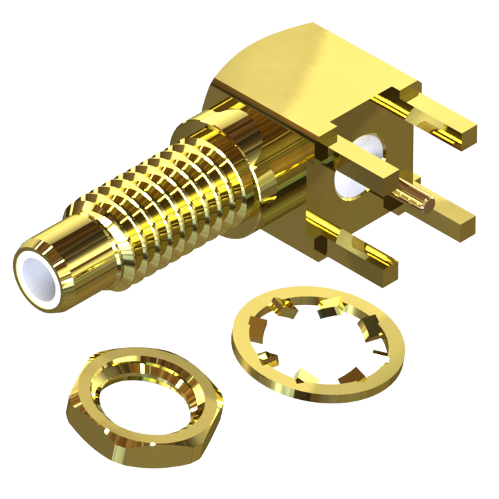
Select View 3D Model to load the interactive model.
2D Drawing
SMCJ-06AL-BT-01-Au — dimensions, PCB mounting pattern and panel cutout. Click the drawing to view the full-size image.
PRODUCT SPECIFICATIONS
| Attributes | Details |
|---|---|
| Part Number | SMCJ-06AL-BT-01-Au |
| Series | SMC |
| Gender | Jack (Male Pin) |
| Orientation | Right angle (R/A) |
| Mounting | PCB; bulkhead rear mount (B/H) |
| Weight | 4.28 g |
ELECTRICAL SPECIFICATIONS
| Attributes | Details |
|---|---|
| Impedance | 50 Ω |
| Frequency range | DC to 4 GHz |
| Working voltage | 335 Vrms |
| Dielectric withstanding voltage | 1,000 Vrms |
| Insulation resistance | 1,000 MΩ |
MECHANICAL & MOUNTING SPECIFICATIONS
| Attributes | Details |
|---|---|
| Overall length / height | 20.15 mm / 11.45 mm |
| Body size (square) | 7.00 mm |
| Maximum panel thickness | 2.80 mm |
| Thread shown on drawing | #10-32 UNF-2A |
| PCB mounting holes | 5.08 mm square pattern; 4 × Ø1.70 mm holes |
| PCB center hole / contact pin | Ø1.20 mm / Ø0.96 mm |
| Panel mounting hole | Ø5.00 mm; flat 4.50 mm |
| General drawing tolerances | ±0.15 mm; angles ±3.0° |
MATERIALS & FINISHES – COMPLETE DRAWING BOM
| Item | Component | Material | Finish | Qty |
|---|---|---|---|---|
| 1 | Nut | Brass | Gold | 1 |
| 2 | Teeth washer | Brass | Gold | 1 |
| 3 | Body | Brass | Gold | 1 |
| 4 | Insulator | PTFE | — | 1 |
| 5 | Contact pin | Brass | Gold | 1 |
| 6 | Body | Brass | Gold | 1 |
| 7 | Insulator | PTFE | — | 1 |
ENVIRONMENTAL & COMPLIANCE INFORMATION
| Attributes | Details |
|---|---|
| Temperature rating | −65 °C to +165 °C |
| RoHS | (see product page for current document) |
PRODUCT DOCUMENTS
View technical documents for SMCJ-06AL-BT-01-Au.
2D Drawing
Dimensions, PCB layout and panel mounting details.
Engineering drawing · PDF
Data Sheet
Product overview, specifications and materials.
Product Data Sheet · PDF