

説明
PRODUCT OVERVIEW
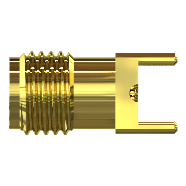
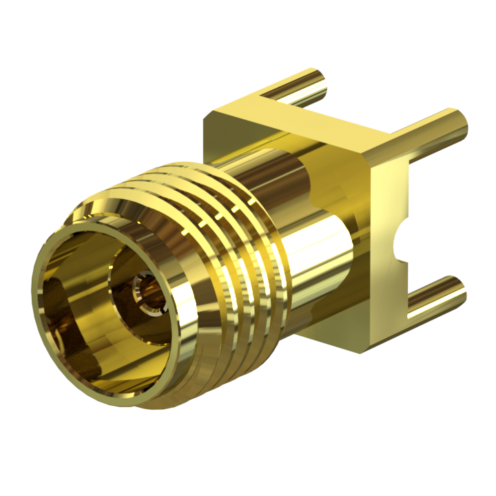
The KJ-05-BK-01-Au is a 50 Ω 2.92mm (K Band) jack receptacle specified from DC to 40 GHz. It provides a straight coaxial interface for a PCB RF connection, combining a threaded mating port with the surface-mount configuration identified in the engineering drawing.
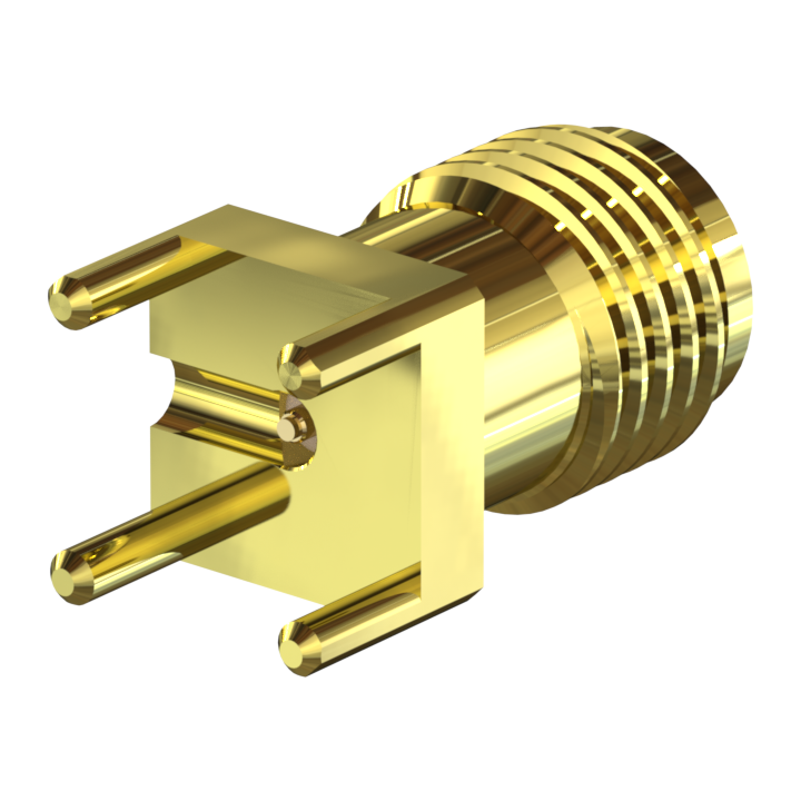
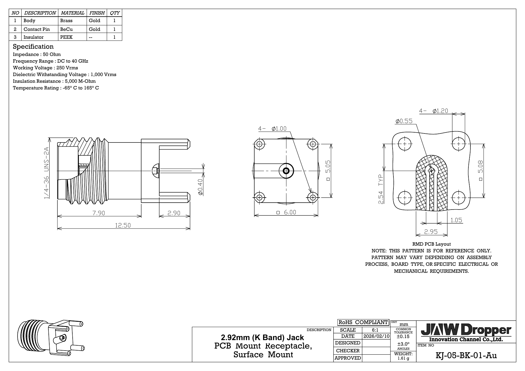
The 1/4-36 UNS-2A external thread supports screw-on mating engagement. A 6.00 mm square body and 12.50 mm overall length define the space required around the connector. Four body posts and a central PCB contact provide the mechanical and signal interface shown in the recommended board layout.
The assembly uses a gold-finished brass body, a gold-finished beryllium copper (BeCu) contact and a PEEK insulator. Its 1.61 g weight and specified -65 °C to +165 °C temperature range support component selection for compact microwave modules and board-level RF test hardware.
For implementation, review the connector geometry together with the PCB stack-up, transmission-line transition and assembly process. The reference PCB pattern may require adaptation to the board design; the complete mounted RF path should be verified over the intended operating band.
Features
- DC to 40 GHz frequency coverage: a 50 Ω connector option for broadband RF and microwave board interfaces.
- Threaded coupling: a 1/4-36 UNS-2A external thread provides screw-on mating engagement.
- Compact board footprint: the 6.00 mm square body helps plan connector placement in dense RF layouts.
- Straight PCB configuration: the mating axis and central PCB contact follow a straight path; four body posts locate the receptacle at the board.
- Gold-finished metal components: the body is brass and the contact is BeCu, with gold finish specified for both parts.
- PEEK insulation: the drawing identifies the insulator material and a -65 °C to +165 °C assembly temperature rating.
- Documented integration geometry: the drawing includes connector dimensions and a reference PCB pattern for layout review.
Key Technical
| Attributes | Details |
|---|---|
| Series | 2.92mm (K Band) |
| Gender | Jack |
| Orientation | Straight |
| Mounting | PCB; surface mount |
| Weight | 1.61 g |
| Impedance | 50 Ω |
| Frequency range | DC to 40 GHz |
| Working voltage | 250 Vrms |
| Dielectric withstanding voltage | 1,000 Vrms |
| Insulation resistance | 5,000 MΩ |
| Coupling | 1/4-36 UNS-2A threaded |
| Body / contact finish | Gold |
| Insulator | PEEK |
Applications
Potential uses for this PCB receptacle include the following RF development and equipment interfaces. Selection depends on the required frequency band, mating arrangement and completed board performance.
- Microwave test and measurement: board-level RF ports for connecting a device under test to external test hardware.
- Laboratory evaluation fixtures: prototype and characterization boards that require a threaded 2.92mm (K Band) interface.
- SATCOM RF module development: candidate PCB interfaces for microwave signal paths within the specified operating range.
- Compact high-frequency PCB modules: board-to-coaxial transitions where a straight receptacle and small body suit the mechanical layout.
Validate the connector-to-board transition, assembly process and system requirements for the intended application.
Interactive 3D View
Explore the connector from every angle. Drag to rotate, scroll or pinch to zoom.
Select View 3D Model to load the interactive model.
2D Drawing
Click the drawing to view the full-size image, or open the original PDF.
PRODUCT SPECIFICATIONS
| Attributes | Details |
|---|---|
| Part Number | KJ-05-BK-01-Au |
| Series | 2.92mm (K Band) |
| Gender | Jack |
| Orientation | Straight |
| Mounting | PCB; surface mount |
| Weight | 1.61 g |
ELECTRICAL SPECIFICATIONS
| Attributes | Details |
|---|---|
| Impedance | 50 Ω |
| Frequency range | DC to 40 GHz |
| Working voltage | 250 Vrms |
| Dielectric withstanding voltage | 1,000 Vrms |
| Insulation resistance | 5,000 MΩ |
Ratings are transcribed from the supplied engineering drawing. Test conditions and min./typ./max. qualifiers are not specified.
MECHANICAL & MOUNTING SPECIFICATIONS
| Attributes | Details |
|---|---|
| Overall length | 12.50 mm |
| Body size (square) | 6.00 mm |
| Thread shown on drawing | 1/4-36 UNS-2A |
| Body posts | 4 × Ø1.00 mm; 2.90 mm projection |
| PCB contact diameter | Ø0.40 mm |
| Recommended PCB holes | 4 × Ø1.20 mm on 5.08 mm square pattern |
| Reference central feature | Ø0.55 mm; see PCB layout |
| General drawing tolerances | ±0.15 mm; angles ±3.0° |
The recommended PCB pattern is a reference. Adapt it to the assembly process, board type and electrical or mechanical requirements.
MATERIALS & FINISHES – COMPLETE DRAWING BOM
| Item | Component | Material | Finish | Qty |
|---|---|---|---|---|
| 1 | Body | Brass | Gold | 1 |
| 2 | Contact Pin | BeCu | Gold | 1 |
| 3 | Insulator | PEEK | — | 1 |
ENVIRONMENTAL & COMPLIANCE INFORMATION
| Attributes | Details |
|---|---|
| Temperature rating | -65 °C to +165 °C |
PRODUCT DOCUMENTS
View technical documents for KJ-05-BK-01-Au.
Data Sheet
Product overview, specifications and materials.
Product Data Sheet · PDF